Bill Bradford - Salt Lake City, Utah, USA - DN40bp - bill@k7ea.com
DIY Antenna for 30 Meters (and 12 Meters, and 6 Meters)
The antenna described in this article is a ground plane type quarter wave vertical designed to be used on the 30 meter (10.100 – 10.150 Mhz ) amateur radio band. As a bonus it tunes up very nicely on the 12 and 6 meter bands. There are hundreds of articles and tons of information about antennas available to us all today, and this antenna is a result of my research and what I thought would work best in a ham application. It is a pretty great antenna.
See Parts List here.
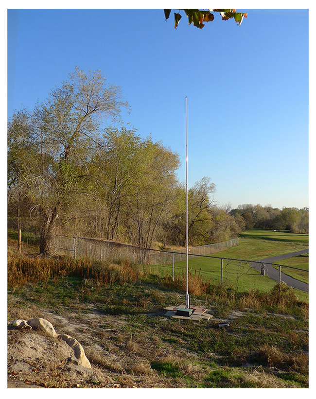
The antenna consists of three main components: The 24 foot vertical mast, the base assembly, and a ground counterpoise system (the radial wires). Read and study all of this first, then go step by step as you build your own.
The $64 question: How many radials? Without a good ground system a vertical is just a dummy load.
This antenna design uses 64 radials, each 23 feet long to provide a pretty great counterpoise for the main radiator. After poring over lots and lots of information regarding “what is the optimum number of radials” I decided the point of diminishing returns was 64. Any less dropped performance significantly, and any more didn’t give that much back for the cost and complexity.
At resonance, the antenna will be a bit less than 50 ohms impedance. Tune it for lowest SWR at center band, that will show as 1:1.4 or so but no worries. Use the balun and do the counterpoise system right, and this antenna will suck the power FETs right out of their sockets from your rig. And it’s almost flat from end to end of band.
Prior Planning Prevents Piss Poor Performance . . .
An ideal location would be a minimum fifty foot diameter circle area, away from structures and thick vegetation, flat as possible, with grass or low ground cover. But who has ideal, so go for the best you can.
Layout the placement of antenna mast and ground radials. Use a 24 foot string and some stakes to outline the extent of the ground plane. When the project is complete, there will be 64 evenly spaced radials around the center.
Layout the feed line run. This may be the hardest work of the project because we want to bury the line inside 1” PVC pipe, from the antenna base to at least outside the radial area. This keeps the coax below and away from the radials, and makes for a clean install. And use good coax like LMR-400, it is super low loss at 10Mhz and water resistant.
Plan the adaptor plate and U-bolts to match the base post you choose. I used regular pipe, but recommend galvanized. Length of the PVC insulator needs also to be determined.
When clamping mast sections, locate the clamp in the center of the slit area and don’t over tighten. Use the anti-oxidant on each joint.
Refer to the drawing and pictures to clarify design and parts placement. Make sure your LoTW is ready for all the great contacts you Will make.
The base: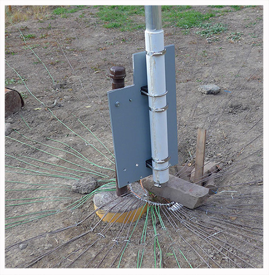
Make a 32” deep hole for the 12” diameter sonotube. We want solid, below the frost line here. The post ought to go to the bottom and rise above ground to just above adaptor plate. Place a few inches of gravel at bottom of hole and fill with good quality post mix. Mix it in a wheel barrow Thick, not runny. Do not dump dry premix in hole and add water. Doing that will make it weak and cause your iambic keyer to stutter. Make sure it is vertical. Let it set up a week or so before installing the antenna.
The adaptor plate:
This is customized depending on your sources. I used two 7-unit 19” aluminum rack panels ( 19” x 14”), back to back for rigidity. Steel would be ok but harder to drill the U-bolt holes. Decide what post you will use. Make sure the U-bolts are the right size for the post. Use saddle clamp U-bolts on the PVC insulator.
Layout and drill the holes for U-bolts and it is ready. Be accurate as this will affect our ability to make the antenna vertical.
The radiator assembly consists of two parts, the antenna mast and the PVC insulator:
The antenna mast is five telescoping aluminum sections, going down from 2” to 1.5” outside diameter. Layout the sections, equalizing the overlaps to come up with a total length of 24 ft. even. This length is calculated for 10.125 Mhz, and is very close to what I ended up with. Three quarters of an inch mast length equals about 50 Khz, so be precise. Use the anti-oxidant between sections as instructed on the label. Install clamps tight but do not distort them. My OM would say, “tighten them a quarter turn before they break . . .”
Make sure the bottom section has plenty of overlap (plus or minus 8 inches) so it can be adjusted for length later. I cut 2” off the top section to eliminate the slit end, and installed the cap. Mark where lower and next section meet, then remove the lower section for the next step. Yes remove the lower section before going on.
The PVC insulator is a length of 2” PVC pipe, cut end to end (jig saw) to allow for expansion for fitting over the lower 2” section of antenna mast. Length to determined by your installation, but it needs to project past the adaptor plate top and bottom (see pic). It insulates the mast from the adaptor plate and base.
Use hose clamps around the PVC to clamp it around lower section. Install the band clamp (with stud) to bottom of antenna lower section, right below the PVC insulator. This will be the feed point for the antenna.
Apply high grade outdoor sealant/caulk to the split in PVC and around ends. Let it dry and set up. When it is all dry, bolt it up to the adaptor plate and adjust height so bottom of the assembly sits as shown in the drawing and pictures. Do not final tighten yet.
Now bolt entire assembly to the base post, leaving clearance on bottom for connection to balun. Make it vertical and tighten all the bolts. When all that is secure and plumb, install the top four sections of mast (all ready assembled) to the place prior marked, and clamp semi tight.
The ground counterpoise system (radials):
I made and soldered the radial wire bundle in my garage, with coiled wires, and then moved it to the antenna site and unrolled things there. I used stranded, insulated #14 from the hardware store, 14 THHN, and you will need just over 1,500 feet of it. Other types wire should be fine (stick with copper or aluminum), I picked what I did for durability.
Measure and cut the first (and pattern) radial, then use it to measure out the other 63. I made them 24 ft. 6 inches, and stripped the last four inches for connection to central ring. Coil each one separately and use a wire tie else you will have a Giant mess forthcoming. Leave two or so feet loose on the bare end to give elbow room when they are all connected to the ring.
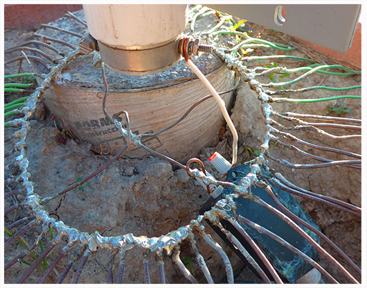
The center ring is a 10” to 12” diameter coil of #12 or #14 solid bare wire, several turns, wound together (See picture) . Lay out the connection points for each of the 64 wires so they are equally spaced around the ring, then wind and solder each to the ring. Tin, or pre-solder, the ends before winding. Get a good big soldering iron, this will kill off a regular gun.
Solder two more short ( 24”) bare solid #12 wires to the ring for later connection to the balun and the adaptor plate.
After all 64 radials are soldered and coiled, figure out a way to carry it all to the antenna site (I slid mine on a 4x4 ft. plywood) and center the ring under the antenna radiator. Gently stake the ring down and begin unrolling radials. Make it symmetrical with even spacing of all wires. Use wire stakes on the ends and throughout the area as needed.
Do Not pull the radial wires tight, leave a bit of slack for a foot print or movement. Leave some slack trust me. Soon any vegetation will envelop the wires and they will become safe and invisible.
Connect one of the short bare wires from the ground ring to the adaptor plate, using one of the U-bolt bolts and an extra nut. The other bare wire will go to the ground connection of the balun (see pic).
 The feed assembly and tuning:
Connect the 1:1 balun, black terminal to ground ring using one of the short wires previously soldered on to the ring, and red terminal to band clamp stud, the antenna mast, using a piece of solid #12. Make the wires as short as possible, while leaving some room to work and weatherproof it later.
At this time, an SWR meter can be used (connected to balun via short coax) to adjust antenna length. Loosen the lowest section, and make small (quarter inch) adjustments to the length to find lowest SWR point at center of band 10.125 Mhz. The antenna is very flat across the band, and I see no need to favor one end or the other. Tighten the section down.
Typical feed impendence for a ground plane like this is a bit less than 50 ohms (theoretical 32 ohms). But again, no worries, tune for lowest SWR (about 1:1.4) and this will be one hot antenna.
Coax should now be emerging from the 1” PVC pipe at the base of the antenna, other end your shack and rig. Connect it to the balun and protect connection with silicon tape. I wrapped by balun and connections with plastic sheeting and waterproof tape, and covered the balun and ring with a sprinkler valve box. I applied several coats of spray plastic coat to the ground ring and soldered portion of radials.
While not the goal of this project, the antenna tunes up very nicely on 12 meters (24.890 Mhz – 24.990 Mhz) and also OK on 6 meters with a little tuner help.
See you on 30. Or 12. Or 6.
Copyright 2017 K7EA